PDP-8/I · Volume 8
PDP-8/I — Volume 8 — I/O, Paper Tape & Peripherals
How a twelve-bit processor with a single accumulator reached out to the world — through one opcode, a clattering Teletype, ribbons of punched paper, a lone interrupt wire, and a back room full of spinning tape and disk.
8.1 About This Volume
Every volume so far has looked inward — at the twelve-bit word, the single accumulator, the core memory that holds a program through the night, the front panel by which a person and a bare machine first meet. Volume 7 closed with the RIM loader springing to life and pulling a paper tape into core, and in that one act it crossed a boundary: for the first time the PDP-8/I was no longer talking to itself, but reaching out to a device in the room and pulling data across the gap. This volume is about that gap, and everything that lived on the far side of it.
The PDP-8/I’s relationship with the outside world is built on an idea of almost startling economy. There is no I/O bus protocol to learn, no memory-mapped device registers, no DMA controller to program in the base machine — there is one opcode, number 6, the IOT (“input/output transfer”) instruction met in Volume 5, and with it the processor can address a peripheral, prod it, and trade a word. Around that single instruction DEC built a whole zoo of devices: the everyday ASR-33 Teletype that was the machine’s keyboard, printer, and tape station all at once; the optional high-speed paper-tape reader and punch for labs that did serious tape work; the elegant single-line program interrupt that freed software from standing and watching; and beyond them the wider peripheral catalogue — DECtape, line printers, fixed-head disks, scope displays, A/D converters — that turned a bare twelve-bit processor into a laboratory’s brain or a factory’s controller.
We start where the machine starts: with the IOT instruction itself, and the patient, almost humble style of programmed I/O it implies — issue a command, then wait, watching a single status bit until the slow mechanical world is ready. From there we meet the devices in turn, and finally the interrupt system that lets the processor stop waiting and start working, attending to the peripherals only when they call. By the end you will understand not just how the 8/I moved a character or a block of data, but why its whole I/O philosophy — minimal in hardware, generous in what software could build on it — was the thing that made it the most adaptable small computer of its age.
8.2 The IOT instruction and programmed I/O
Recall from Volume 5 the eight opcodes packed into the top three bits of every PDP-8 word, and that opcode 6 is IOT — input/output transfer. For the six memory-reference and operate opcodes, the lower nine bits address memory or select micro-operations. Under IOT they mean something else entirely: they name a device and tell it what to do. The nine bits split into two fields.
   IOT instruction format (opcode 6)

    0   1   2   3   4   5   6   7   8   9  10  11    bit
   +---+---+---+---+---+---+---+---+---+---+---+---+
   | 1   1   0 | d   d   d   d   d   d | p   p   p |
   +---+---+---+-----------------------+-----------+
    \____ ____/ \_________ ___________/ \____ ____/
         v                v                  v
     opcode 6        device address      control /
     (= 110)          (6 bits, 3-8)     pulse bits
                      64 devices         (3 bits, 9-11)
Bits 0–2 are the opcode, fixed at 110 (octal 6). Bits 3–8 — six bits — are the device address, enough to name 64 distinct devices, each peripheral wired to recognize its own number and ignore the rest. Bits 9–11 — three bits — are device-specific control or “pulse” bits. When the processor executes an IOT it puts the device address onto the I/O lines, every device compares it against its own assigned number, and the one that matches springs to attention; the three low bits then tell that device which of up to three actions to perform. In the machine’s timing these three bits are generated as three successive I/O pulses (DEC called them IOP1, IOP2, IOP4), so a single IOT can fire one, two, or all three in sequence — which is why one instruction can both clear a flag and read a word in one stroke.
This is the whole I/O instruction set. There is no separate “read” or “write” opcode; a device simply decides what each of its three pulses means. By convention a peripheral’s three bits are used for a small, regular menu: skip if the device’s flag is set, clear the flag (and/or clear the accumulator), and transfer a word between the accumulator and the device. From these primitives all I/O is built.
The linchpin of the whole scheme is the device flag. Every peripheral carries a one-bit flag flip-flop that means, simply, “I am ready” — a reader flag goes up when a character has been read and is waiting; a printer flag goes up when the printer has finished the last character and can accept another. The processor runs millions of times faster than any mechanical device, so it cannot just blunder ahead; it must wait for the flag. And the IOT scheme gives it exactly one way to test a flag: a “skip if flag set” IOT, an instruction that does nothing but skip the next instruction when the device’s flag is up. That single conditional is the seed of the classic programmed-I/O idiom — the busy-wait loop:
   / read one character from the Teletype keyboard/reader
   /
   KSF             / skip if Keyboard Flag is set (char ready?)
   JMP .-1         / not ready: jump back and test again
   KRB             / flag up: Read the Buffer into AC, clear the flag
The shape is unmistakable and appears wherever a PDP-8 touches a slow device. KSF (“Keyboard Skip if Flag”) tests the reader flag; if the flag is down, the skip does not happen and control falls into JMP .-1 — “jump to here-minus-one,” i.e. back to the KSF — and the machine sits in that two-instruction loop, testing the flag over and over, spinning, doing nothing useful but waiting. The instant a character arrives the flag rises, the next KSF skips over the JMP, and the program drops through to KRB (“Keyboard Read Buffer”), which copies the character into the accumulator and clears the flag so the loop is armed for next time. Output is the mirror image: load the accumulator with a character, issue the “transmit” IOT, then spin on the printer’s “skip if done” flag until the slow print head has finished before sending the next.
This is programmed I/O, and its defining feature is that the processor’s full attention is consumed while it waits. At ten characters a second from a Teletype, the processor spins through that two-instruction loop hundreds of thousands of times between one character and the next — an enormous waste of a machine that could execute an instruction every microsecond and change. For a program whose only job is to read a tape it does not matter; the machine has nothing better to do. But for anything that wants to compute while it talks to the world, busy-waiting is intolerable, and it is precisely this waste that the interrupt system, later in this volume, exists to eliminate. First, though, the devices the program is waiting on.
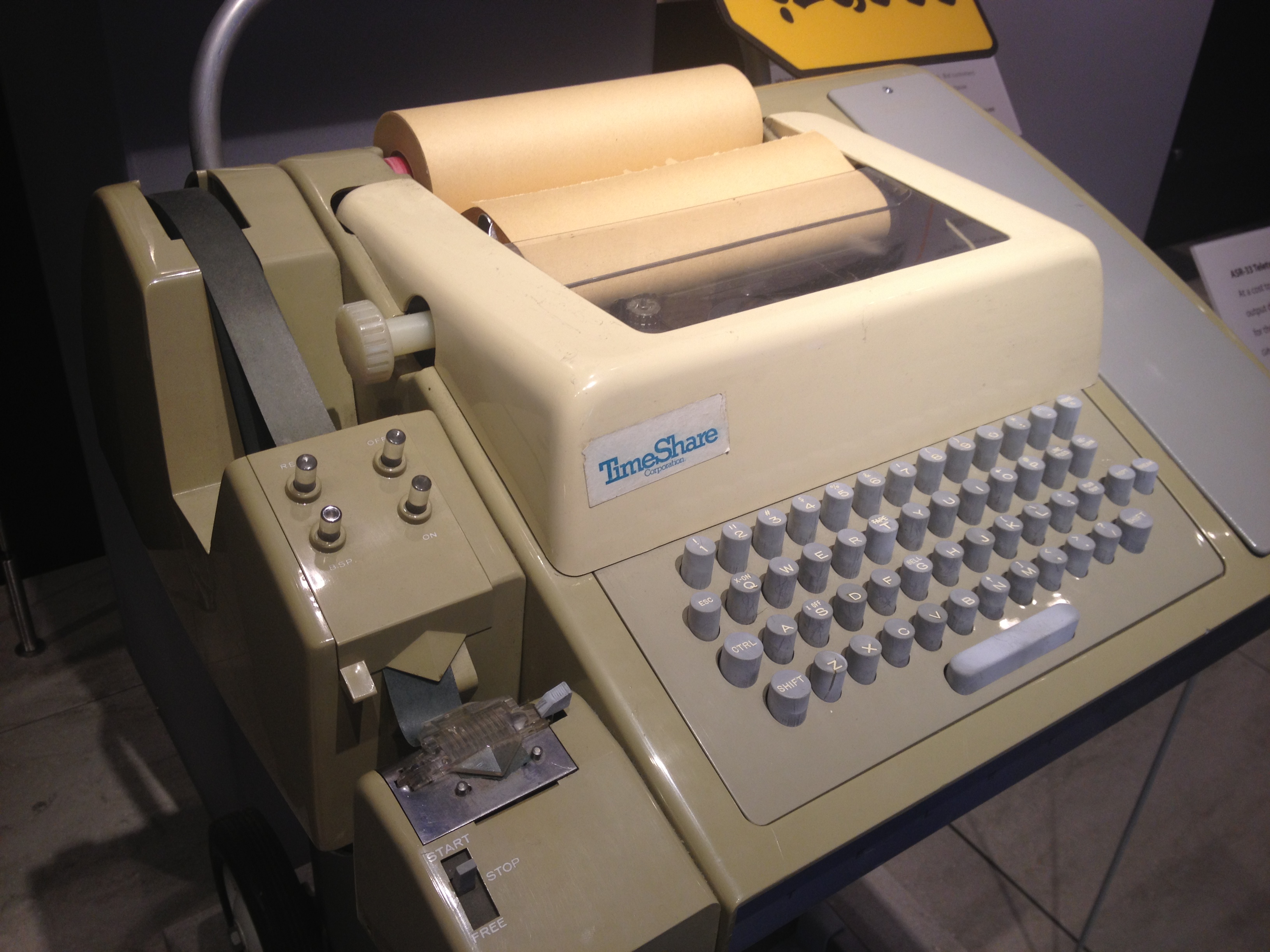
8.3 The ASR-33 Teletype
The standard console of the PDP-8/I — the thing a user actually sat at — was a Teletype Model 33 ASR, and it is impossible to overstate how central this clattering, oil-smelling electromechanical machine was to the daily life of the computer. “ASR” stands for Automatic Send-Receive, and the name is a promise: a single beige steel unit combined, in one electromechanical mechanism, four devices — a keyboard to type input, a printer (the teleprinter) to print output on a roll of paper, a paper-tape reader to read punched tape, and a paper-tape punch to punch it. Keyboard and printer, reader and punch: input and output, human-readable and machine-readable, all in one box that DEC could ship as the machine’s console for a few hundred dollars.
It was, by the standards of the processor it served, achingly slow. The Model 33 ran at ten characters per second — 110 bits per second in eleven-bit frames (one start bit, seven data bits, a parity bit, and two stop bits) — the speed of a brisk typist and no faster, set by the spinning mechanical type cylinder and the synchronous motor that drove the whole assembly. Every character the PDP-8/I printed, every character a user typed, every frame of a paper tape read through the ASR’s reader, crossed at that stately ten-per-second pace. The processor spent essentially all of its time, when talking to the Teletype, waiting on it.
The Teletype spoke ASCII — the seven-bit code, transmitted as eight bits with a parity or mark bit, that the Model 33 helped make a de-facto standard. The PDP-8, with its twelve-bit word, simply stored each eight-bit character right-justified in a twelve-bit word, the top four bits zero (or, in packed text, two six-bit characters to a word). This impedance match — an eight-bit character world living inside a twelve-bit machine — is a recurring texture of PDP-8 programming, and it is why so much PDP-8 string handling masks, shifts, and packs.
To the programmer the ASR-33 appeared as two independent devices, each with its own flag and its own quartet of IOTs, because the keyboard/reader side and the teleprinter/punch side could run at the same time. The keyboard and low-speed reader answer to device 03:
- KSF (
6031) — Keyboard Skip if Flag: skip if a character has been received. - KCC (
6032) — Keyboard Clear: clear the flag and clear the accumulator. - KRS (
6034) — Keyboard Read Static: OR the character into AC without clearing the flag. - KRB (
6036) — Keyboard Read Buffer: clear AC, read the character in, and clear the flag — the everyday “read a character” instruction, equal to KCC + KRS in one stroke.
The teleprinter and punch answer to device 04:
- TSF (
6041) — Teleprinter Skip if Flag: skip if the printer is done with the last character. - TCF (
6042) — Teleprinter Clear Flag: clear the done flag without sending anything. - TPC (
6044) — Teleprinter Print Character: send the character in AC to the printer/punch. - TLS (
6046) — Teleprinter Load and Start: load AC into the printer buffer, start printing, and clear the flag — the everyday “print a character” instruction.
With these eight instructions a programmer had the entire console: KSF/JMP .-1/KRB to read a key, TLS/then spin on TSF to print one. The Teletype’s reader was, of course, the very device the RIM loader of Volume 7 was driving — those 6031/6032/6036 codes in the loader’s octal are these same keyboard IOTs — and its punch was how a user saved a program, punching the assembled binary out onto a fan-folded ribbon of tape to be read back another day. For the great majority of PDP-8/I sites, this one machine — keyboard, printer, reader, punch — was the input/output system. Everything else was a luxury.
8.4 High-speed paper tape
Ten characters a second is fine for typing and tolerable for printing, but it is agony for moving real volumes of data. A modest program of a few thousand words, distributed on paper tape, takes minutes to read through the Teletype’s sprocket-driven reader; an assembler reading source, then a tape of object code, then writing a listing, could chew up a coffee break per pass. For any site that lived on paper tape — and in the late 1960s, before disk was cheap, that was most sites doing serious work — the Teletype’s reader and punch were a bottleneck worth paying to remove.
The remedy was the high-speed paper-tape reader and punch, sold across the 8/I era under designations like the PC04 (the combined reader/punch) and read by a photoelectric mechanism rather than the Teletype’s mechanical feelers. Instead of sprocket pins clicking the tape forward one frame at a time, the high-speed reader pulled the tape smoothly past a row of photocells and a light source, sensing the punched holes optically, and it ran at about three hundred characters per second — thirty times the Teletype’s pace. A tape that took a minute and a half through the ASR went by in three seconds. The matching high-speed punch was faster than the Teletype’s too, punching on the order of fifty characters per second. Labs that compiled and reassembled all day, that read large data tapes, that wanted to iterate, bought the high-speed reader and never looked back; it paid for itself in saved hours within weeks.
Crucially, the high-speed reader and punch were separate devices from the console, with their own device codes — the reader at device 01, the punch at device 02 — and their own flags and IOTs (RSF/6011 to skip on the reader flag, RRB/6012 to read the buffer, RFC/6014 to fetch the next character; PSF/6021, PLS/6026 and kin on the punch). A program could therefore have both the slow Teletype and the fast reader present at once, and choose between them. This is exactly why Volume 7’s RIM loader came in two variants: the low-speed version drove the Teletype reader at device 03, while a near-identical high-speed variant — beginning 7756/6014, 7757/6011 — drove the photoelectric reader at device 01. The structure of the loader was the same; only the device codes changed, because the only difference between the two readers, as far as the program could see, was which six-bit device number answered the IOT.
8.5 The interrupt system
Programmed I/O works, but its busy-wait loops are a scandal of wasted time. A PDP-8/I spinning on KSF while a user dawdles at the keyboard is a million-dollar-an-hour mind staring at a doorbell, doing nothing else until it rings. The cure — the thing that lets the processor forget about a slow device and get on with computing, attending to the device only when it actually needs service — is the program interrupt, and the PDP-8’s version is a model of minimalism.
There is exactly one interrupt line, shared by every device on the machine. Any peripheral that wants attention — its flag has come up, a character has arrived, the printer is ready for more — can raise that single line. The interrupt system as a whole is turned on and off by two IOTs: ION (6001, “interrupt on”) enables it, and IOF (6002, “interrupt off”) disables it. While interrupts are enabled, the processor checks the line at the end of each instruction; when it finds the line raised, it does something beautifully simple. It disables further interrupts (so the handler cannot itself be interrupted before it is ready), and then it forces, in hardware, the equivalent of a JMS to location 0000 — a jump-to-subroutine into the very bottom word of memory, field 0. As Volume 5’s JMS does, it stores the interrupted program’s return address (the program counter) into location 0 and begins executing at location 1. The running program has been frozen mid-stride, its return address tucked safely away, and control handed to whatever interrupt-service routine the programmer placed at location 1.
That is the entire hardware mechanism. Notice what it does not do: it does not tell the handler which device interrupted. There is no vector, no priority encoder, no table of per-device entry points — the single line says only “some device needs you,” never which. The PDP-8 leaves that to software, and the software answer is the skip chain (or “poll”): the interrupt routine, having been entered, simply walks down a list of “skip if flag set” IOTs, asking each device in turn — KSF? TSF? RSF? — “was it you?” The first device whose flag is found up is serviced, and the order of the tests is the priority scheme: whichever device you test first is the one that gets attended to first when two interrupt at once. Having serviced the requester and cleared its flag, the routine re-enables interrupts with ION and returns to the interrupted program by jumping indirectly through location 0 (JMP I 0) — landing exactly where the interrupt struck, the interrupted program none the wiser.
The contrast with programmed I/O is the whole point. Polling (busy-wait) ties the processor to a single device and burns every cycle until that device is ready — simple, deterministic, and perfect when the machine has nothing else to do (a loader, a dedicated controller). Interrupt-driven I/O inverts the relationship: the processor goes off and computes, and the devices call it, briefly borrowing the processor only at the instant they need a byte moved. The cost is the skip chain — software must still poll, but only after an interrupt, and only to find which of a handful of devices spoke, not to wait. With interrupts a PDP-8/I could run a compute job in the foreground while a paper tape clattered in, or service a keyboard, a printer, and a real-time clock all “at once,” each interrupting, being serviced in a few microseconds, and releasing the processor. It is the single feature that lets one twelve-bit accumulator appear to do many things at once, and it is the foundation on which every PDP-8 operating system and real-time application was built.
8.6 The wider peripheral catalogue
The Teletype and the paper-tape stations were the machine’s everyday voice, but the IOT scheme’s real gift was extensibility: with 64 device addresses available and a uniform flag-and-pulse model, almost anything could be hung off a PDP-8/I and driven by a handful of IOTs. The catalogue that grew up around the machine is what turned it from a bare processor into a laboratory instrument, a timesharing host, and an industrial controller.
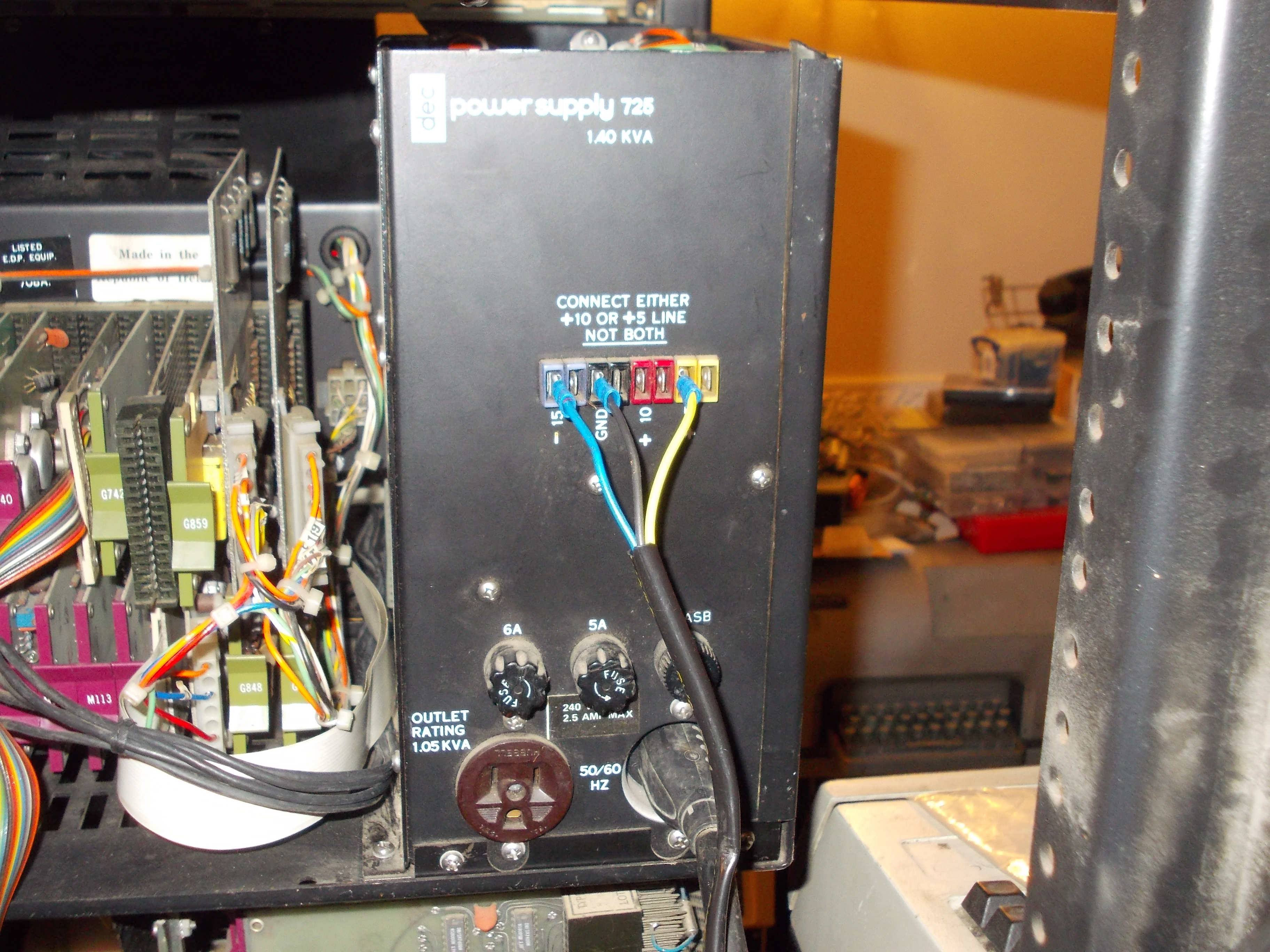
DECtape was the most beloved member of the family, and deservedly so. It was a small, fat reel of ¾-inch tape, laminated mylar with the magnetic oxide sandwiched inside so it could not flake off, driven by a TU55 (single) or TU56 (dual) transport through a TC01/TC08 controller. What made DECtape special was that, unlike ordinary computer tape, it was block-addressable: the tape was pre-formatted at the factory with a fixed structure of numbered blocks (recorded redundantly across its ten tracks — data, mark, and timing — so a dropout, or even a quarter-inch hole punched clean through, would not lose a bit), and the drive could be told to find block 47 and read or write it, in either direction, the same way one might address a primitive disk. This made DECtape feel less like a tape and more like a slow, removable, utterly dependable little drive — you could rewrite a single block in the middle of a tape without disturbing its neighbors. It held a few hundred kilobytes, and its legendary reliability (you could drop a reel, step on it, leave it in a drawer for years) made it the medium people trusted for their files and their systems when disks were still exotic and expensive.
The line printer gave a site real output speed: where the Teletype managed ten characters a second, a line printer slammed out a full line at a time, hundreds of lines a minute, for listings, reports, and program output — the difference between watching your assembler listing crawl out over minutes and having it stack up in the tray.
Disk storage, when a site could afford it, transformed the machine. DEC offered fixed-head disks like the DF32 and the larger RF08 (a head-per-track disk, fast and seek-free), and later the moving-head RK8 cartridge disk — random-access storage measured in hundreds of thousands of words, fast enough to swap programs and hold an operating system’s files. Disk is what made PDP-8 timesharing (multiple Teletypes, multiple users) and disk-based operating systems practical; it is the step beyond DECtape that turned the 8 into a genuine multi-user machine.
The VR14 and related scope displays gave the machine an eye: a point-plotting CRT the program drew on by sending X/Y coordinates through IOTs, painting graphs, waveforms, and crude pictures point by point — the ancestor of every computer display, and the natural partner for the scientific work the 8 so often did.
And underpinning the 8/I’s deepest identity as a laboratory and industrial machine were the analog and process interfaces: A/D converters that let the machine sample a voltage — a temperature, a pressure, a biological signal, an instrument’s output — and pull the real, continuous world into its twelve-bit registers; D/A converters to push values back out; and banks of digital I/O lines to read switches and drive relays. With an A/D front end and an interrupt-driven program, a PDP-8/I became the brain of an experiment or a production line: sampling sensors on a clock interrupt, computing, and actuating — exactly the role that sold thousands of them into labs, hospitals, and factories. It is the same uniform IOT-and-flag model throughout: whether the device on the far side of opcode 6 was a clattering Teletype, a spinning DECtape, or an analog-to-digital converter watching a patient’s heartbeat, the processor talked to it the same patient way — name the device, fire a pulse, wait for the flag. That single, frugal idea is what let one small computer reach out and touch the entire world.
Sources
- Doug Jones, PDP-8 documentation pages (University of Iowa) — the IOT instruction format (opcode 6, six-bit device field in bits 3–8, three I/O pulse bits in bits 9–11), the device-flag/skip-chain model, the console Teletype IOTs (KSF
6031, KCC6032, KRS6034, KRB6036on device 03; TSF6041, TCF6042, TPC6044, TLS6046on device 04), the high-speed reader (device 01) and punch (device 02) codes, and the interrupt system. https://homepage.divms.uiowa.edu/~jones/pdp8/ - Doug Jones, “DEC’s 1974 PDP-8 Pocket Reference Card” (University of Iowa) — verbatim octal for the keyboard/reader and teleprinter/punch IOTs, the high-speed reader/punch IOTs, and the interrupt instructions ION (
6001), IOF (6002), SKON (6000), SRQ (6003). The device codes quoted in this volume are taken from this card. https://homepage.divms.uiowa.edu/~jones/pdp8/refcard/74.html - PDP-8/I & PDP-8/L Small Computer Handbook and the PDP-8 Family Paper Tape System User’s Guide (Digital Equipment Corporation), via bitsavers.org — DEC’s own documentation of the IOT instruction, programmed I/O and device flags, the ASR-33 Teletype as console (~10 cps), the high-speed photoelectric reader/punch, the single-line program interrupt (JMS to location 0000, ION/IOF), and the peripheral line (DECtape, line printer, disk, displays, lab interfaces). http://www.bitsavers.org/pdf/dec/pdp8/
- Wikipedia, “PDP-8” — corroborates the IOT device-address/pulse-bit split, the programmed-I/O busy-wait idiom, and the interrupt system: a single shared interrupt line, the processor disabling interrupts and executing a
JMSto location 0000, and the software “skip chain” that serially polls device flags to identify the requester (with skip-chain order setting device priority). https://en.wikipedia.org/wiki/PDP-8 - Wikipedia, “DECtape” — ¾-inch laminated tape, ten tracks (six data, two mark, two timing) with redundant recording, fixed pre-formatted block-addressable structure, bidirectional read/write, ~276 KB capacity, TC01/TC08 controllers with TU55/TU56 transports, and the reliability that made it trusted for early timesharing swap files. https://en.wikipedia.org/wiki/DECtape
- Teletype Model 33 references — the ASR (Automatic Send-Receive) configuration combining keyboard, printer, paper-tape reader, and punch in one unit, running ASCII at ~10 characters per second (110 baud). https://en.wikipedia.org/wiki/Teletype_Model_33
- Figure: “ASR-33 at CHM.agr.jpg,” photograph by ArnoldReinhold at the Computer History Museum, via Wikimedia Commons, licensed CC BY-SA 3.0 — a Teletype Model 33 ASR of the kind used as the PDP-8/I console. https://commons.wikimedia.org/wiki/File:ASR-33_at_CHM.agr.jpg
- Figure: “TU56 DecTape Power Connections,” photograph by tony_duell, via Wikimedia Commons, licensed CC BY 2.0 — a DEC TU56 dual DECtape transport. https://commons.wikimedia.org/wiki/File:TU56_DecTape_Power_Connections_(32655872291).jpg
.jpg)
Comments (0)