PDP-8/I · Volume 4
PDP-8/I — Volume 4 — Architecture I: 12-bit Words, Memory, the Accumulator
Twelve bits, one accumulator, a single carry bit, and a few thousand words of core — the deliberately tiny machine you can hold whole in your head, taken apart one register at a time.
4.1 About This Volume
This is Volume 4 of the fourteen-volume deep dive into the PDP-8/I, and the first of two that take apart the architecture — the abstract machine that, as Volume 3 argued, outlived every set of transistors and chips that ever embodied it. Volumes 1 through 3 told the story from the outside: what the machine was, the company that built it, and the family it belonged to. From here the series goes inside.
The job of this volume is to lay down the foundation on which everything else rests: the shape of the data the machine handles, the organization of the memory it lives in, and the small set of registers a programmer can actually see and touch. Volume 5 will then build the instruction set on top of that foundation — the addressing tricks, the indirection, the famous microcoded operate group. But none of that makes sense until you understand the substrate: a twelve-bit word, a memory carved into pages, a single accumulator that almost everything flows through, a one-bit link that catches the carry, and a program counter to keep the place. That is very nearly the entire machine, and the smallness of the list is not an oversight. It is the design. By the end of this volume you should be able to hold the whole programmer-visible state of a PDP-8/I in your head at once — because that is exactly what its designers intended, and what made the machine teachable, cheap, and beloved.
A warning before we start, aimed at the modern reader: almost every numeric convention here will feel slightly off, because the PDP-8 predates the conventions you grew up with. It counts its bits from the left, groups them in threes rather than fours, and thinks in octal, not hexadecimal. None of this is arbitrary; all of it follows from the one decision at the root of the design — the choice of twelve bits — so that is where we begin.
4.2 The twelve-bit word
The fundamental unit of everything on a PDP-8 is the twelve-bit word. Memory is an array of twelve-bit words; the accumulator is twelve bits wide; an instruction is a twelve-bit word; an address is (very nearly) a twelve-bit quantity. Twelve is the number around which the whole machine is organized, and it is an unusual number. The machines on either side of the PDP-8 in history clustered around powers of two and their neighbors — eight bits, sixteen, eighteen, thirty-six — and twelve sits in none of those families. To understand the PDP-8 you have to understand why DEC chose it, because almost every distinctive feature of the architecture is a consequence of that choice.
Start with what twelve bits buys you. Twelve binary digits encode 2¹² = 4,096 distinct values. Read as an unsigned integer, a word holds a number from 0 to 4,095. Read as a signed integer in two’s complement — the representation the PDP-8 uses for arithmetic — the same twelve bits cover −2,048 to +2,047. That range is the working vocabulary of the machine: it is how many values a word can name, how many words a basic memory can hold, and how far a single number can reach.
Why twelve and not eight or sixteen? The answer is the same frugal calculus that runs through this entire series: cost weighed against utility. Every bit of word width is expensive in a 1960s machine built from discrete logic — every bit means another wire in every data path, another bit of register, another column of adding hardware, another set of sense and drive lines through every plane of core memory. Width is paid for in parts, and parts were what DEC was relentlessly trying to minimize. So the question was not “how wide can we make it?” but “how narrow can we make it and still have a useful general-purpose computer?”
Eight bits was too narrow. A single eight-bit word spans only 0 to 255 — too small to be a useful address into a memory of any size, and too coarse for real laboratory arithmetic. Sixteen bits, the choice that would later dominate the minicomputer world, was comfortably useful — but in the mid-1960s it was also comfortably more expensive, sixteen of everything where twelve might do.
Twelve was the sweet spot DEC and its predecessors had been circling for years. A twelve-bit word is wide enough to hold a genuinely useful integer range and — critically — wide enough to address a respectable 4,096 words of memory directly. It is also a natural fit for the character handling of the era: the machine’s stock in trade was the six-bit character code, and twelve bits packs two six-bit characters into a single word, neatly and without waste. (Those six-bit characters are why the PDP-8 world thinks in octal: three bits make one octal digit, four octal digits make a twelve-bit word, and two octal digits make one six-bit character. The whole notation system falls out of the word size.) Twelve bits was the least DEC could spend while still getting a machine that could address sensible memories and shuffle text — the narrowest word that was still genuinely useful, which is the most PDP-8 design decision imaginable.
Now the convention that trips up every modern reader. DEC numbered the bits of a word from 0 to 11, left to right, with bit 0 the most significant bit — the high-order, leftmost bit — and bit 11 the least significant, rightmost bit. This is the opposite of the convention most programmers learn today, where bit 0 is the low bit on the right and numbering increases toward the high end. On a PDP-8, the leftmost, biggest-valued bit is bit 0. Once you accept it the rest of the documentation reads cleanly — when a manual says “the operation code is in bits 0 through 2,” it means the three high bits on the left — but until you accept it, every bit-field description will seem backwards. Here is the layout to fix it in mind:
      MSB                                               LSB
       |                                                 |
   bit  0    1    2    3    4    5    6    7    8    9   10   11
      +----+----+----+----+----+----+----+----+----+----+----+----+
      | b0 | b1 | b2 | b3 | b4 | b5 | b6 | b7 | b8 | b9 |b10 |b11 |
      +----+----+----+----+----+----+----+----+----+----+----+----+
       2048 1024 512  256  128   64   32   16    8    4    2    1   <- place value
      \________________ one 12-bit word = 0..4095 ______________/
       \___ octal digit _/\__ digit __/\__ digit _/\__ digit __/
            (bits 0-2)      (bits 3-5)   (bits 6-8)  (bits 9-11)
Notice how the four octal digits fall out: each group of three bits is one octal digit (0–7), and four of them name the whole word. A word like 7600 octal is therefore an entirely ordinary way to write a twelve-bit pattern — and you will see numbers like that constantly, because on the PDP-8, octal is the native tongue.
The consequences of the twelve-bit choice ripple through every later volume. Because a word is only twelve bits, a single instruction cannot contain a full memory address and an opcode and its modifier bits — there simply is not room — which forces the page-based addressing scheme we turn to next, and which Volume 5 explores in full. Because a word is only twelve bits, the signed range is small, and any serious arithmetic spills into multiple words, which is exactly what the link bit is for. The whole architecture is, in a sense, a set of clever answers to the constraints that twelve bits imposes. Twelve bits is not just the data size; it is the premise of the design.
4.3 Memory: fields, pages, and the zero page
A PDP-8’s memory is an array of twelve-bit words, and the most natural way to address such a memory is with a twelve-bit address — one word’s worth of bits, naming one word’s worth of locations. Twelve bits of address reach 2¹² = 4,096 words, and that quantity, 4,096 words (universally called “4K”), is the fundamental unit of PDP-8 memory. DEC called one such block a field. A basic PDP-8/I shipped with exactly one field: 4,096 words of magnetic-core memory, addresses 0000 through 7777 in octal.
That is a tidy, self-consistent design — a twelve-bit machine with twelve-bit addresses reaching a 4K memory — but it hides a problem that shapes everything about how the PDP-8 is programmed. Recall that an instruction is also only twelve bits wide. A memory-reference instruction has to spend some of those bits saying what to do (the operation code) and some saying how to do it (modifier bits), which leaves nowhere near twelve bits for the address of the word to operate on. In fact it leaves only seven bits for the address. And seven bits reach only 2⁷ = 128 words — not 4,096.
This is the central tension of PDP-8 memory, and the architecture’s answer to it is the page. The 4K field is divided into pages of 128 words each, and since 4,096 ÷ 128 = 32, a field contains exactly 32 pages, numbered 0 through 31 (octal 0 through 37). A page is simply a 128-word aligned block: page 0 is words 0000–0177 octal, page 1 is words 0200–0377, and so on up to page 37, which is words 7600–7777. The seven-bit address field inside an instruction names a word within a page — an offset of 0 to 127 — and the rest of the address, the choice of which page, comes from elsewhere. Here is the structure:
   One 4K field = 4096 words = 32 pages of 128 words each

   field address (octal)     page (octal)   words in page (decimal)
   +-----------------------+----------------+-----------------------+
   | 0000 .. 0177          | page 0         | the "zero page"  (128)|
   | 0200 .. 0377          | page 1         |                   128 |
   | 0400 .. 0577          | page 2         |                   128 |
   |   ...                 |   ...          |                   ... |
   | 7400 .. 7577          | page 36        |                   128 |
   | 7600 .. 7777          | page 37        |                   128 |
   +-----------------------+----------------+-----------------------+
                                            total: 32 x 128 = 4096

   A 7-bit in-instruction address selects a word WITHIN a page (0..127);
   one "page bit" in the instruction selects WHICH page is meant:

        page bit = 1  ->  the CURRENT page (the page the instruction is on)
        page bit = 0  ->  PAGE 0  (the zero page, words 0000..0177)
That single page bit in the instruction is the hinge. When it is set, the instruction reaches a word on its own page — the high-order bits of the address are taken from the program counter, so “this page” means literally the 128-word block the running instruction lives in. When the page bit is clear, the high-order bits are taken as zero, and the instruction reaches into page 0. This gives page 0 a special, privileged role: it is the one page that every instruction in the entire field can address directly, no matter which page that instruction happens to live on. For that reason it is called the zero page (or simply “the base page”), and it becomes the natural home for a program’s most important shared quantities — frequently used constants, pointers, counters, and the linkage between routines. Page 0 is the common ground, the 128 words of scratchpad that the whole field can always see. Good PDP-8 programming is, in large part, the disciplined management of those 128 precious zero-page words. (To reach anything else — a word on some third page, neither the current one nor page 0 — the program must use indirect addressing, placing a full address in a word it can reach and pointing through it. That mechanism is the heart of Volume 5; here it is enough to know the page system creates the need for it.)
One field of 4K is the basic machine, but the PDP-8 was not strictly limited to 4,096 words. Because the in-word address is at most twelve bits, no single ordinary instruction can name a location beyond 7777 octal — twelve bits simply cannot count higher. To break the 4K ceiling, DEC added an optional Memory Extension Control, which sits above the twelve-bit address and selects which 4K field is currently in use. It does this with a pair of three-bit registers — an instruction field register and a data field register — that supply three additional high-order address bits. Three bits name 2³ = 8 fields, and eight fields of 4K each total 8 × 4,096 = 32,768 words, or 32K, the maximum memory of an extended PDP-8. The twelve-bit address still does the work within a field; the field registers merely say which 4K the program is reading instructions from and which 4K it is reading and writing data in. Special instructions switch fields when a program needs to cross from one 4K bank to another. The full mechanics of field switching, and the way I/O and the extended-memory banks interact, belong to a later volume; for now the essential picture is simple. Memory is a stack of up to eight 4K fields; each field is 32 pages of 128 words; and within any field, page 0 is the page everyone can reach.
4.4 The accumulator
If memory is where the PDP-8 keeps its data, the accumulator is where it does something with it. The accumulator — universally abbreviated AC — is a single twelve-bit register, and it is the working heart of the machine. Nearly every operation the processor performs reads from, writes to, or passes through the AC. To add a number to a running total, you load the total into the AC and add the number to it there. To AND two values, one of them is in the AC and the result lands in the AC. To test whether something is zero or negative, you test the AC. To send a value to a peripheral or store it to memory, it goes out of the AC. The accumulator is the funnel through which the machine’s data is forced to flow.
What is striking about this — and what most distinguishes the PDP-8 from machines a modern programmer is used to — is that the AC is almost the only register there is. A contemporary processor has a generous register file: a dozen or dozens of general-purpose registers, any of which can hold an operand, so that the processor can juggle many values at once without touching memory. The PDP-8 has essentially none of that. There is no bank of general registers. There is the AC, and that is your working space. If you are holding one number in the AC and you need to work on a second, you must first get the first one out — store it back to a memory word — before the AC is free for the next. The accumulator is a single seat, and only one value sits in it at a time.
This is, once again, the frugality of the design showing through. Registers are expensive — each one is a word’s worth of flip-flops plus the logic to route data into and out of it — and the PDP-8 was built to have as few of them as it could possibly get away with. The cost of that minimalism is paid in memory traffic and in programmer effort: PDP-8 code spends a great deal of its time loading and storing values between the single accumulator and memory, because there is nowhere else to keep a working value. A skilled PDP-8 programmer thinks constantly about what is in the AC right now, what needs to be there next, and where to park the thing currently occupying it. The whole rhythm of programming the machine is organized around that one register.
But the same minimalism is also the machine’s pedagogical gift. With one accumulator, there is no question of which register an instruction operates on — there is only one it could mean, so the instruction need not spend bits naming it, which is part of how the instruction set stays so tight. And there is very little hidden state to lose track of. The behavior of nearly every instruction can be described as “it does something to the AC,” which makes the machine almost uniquely easy to reason about, to teach, and to hold whole in the mind. The single accumulator is the architectural embodiment of the PDP-8’s entire personality: do the most with the very least.
4.5 The link bit
A single twelve-bit accumulator has one obvious limitation, and the PDP-8 answers it with one extra bit. When you add two twelve-bit numbers, the true sum can be thirteen bits — the result can be too big to fit, producing a carry out of the top. When you shift the bits of the AC left or right, a bit falls off one end and a gap opens at the other. A bare accumulator has nowhere to put the carry and nothing to feed the gap. So DEC bolted on a one-bit register sitting just above the AC: the Link, abbreviated L.
The Link is, in essence, the carry/overflow extension of the accumulator. When an add overflows the twelve bits of the AC, the carry out of the high end goes into the Link — and, in the PDP-8’s particular style, it complements (flips) the Link rather than simply setting it, a detail that matters for the arithmetic idioms built on top of it. Either way, after an addition the Link tells you whether the sum overflowed: it is the thirteenth bit that the twelve-bit AC could not hold. That single bit is the foundation of multi-precision arithmetic — the technique by which a twelve-bit machine adds numbers far larger than twelve bits. To add two twenty-four-bit numbers, you add the low halves in the AC, note the carry the Link caught, then add the high halves together with that carried bit. The Link is the thread that stitches the separately-added pieces into one correct large sum, exactly the way the carry from one column to the next stitches together a long hand addition.
The Link’s other great role is in rotation. The PDP-8’s shift instructions do not shift the accumulator alone; they treat the AC and the Link together as a single thirteen-bit shift register. A rotate-left instruction shifts all twelve bits of the AC one place toward the high end, moves the bit that falls off the top into the Link, and moves the bit that was in the Link around into the bottom of the AC — a closed thirteen-bit loop. Rotate-right does the same in the other direction. Because the loop is exactly thirteen bits, two of these rotates have tidy, predictable effects, and programmers used them to fish individual bits out of a word, to build multiply and divide routines bit by bit, and to move data through the AC in carefully controlled steps. Picture the combined register:
   +---+   +----+----+----+----+----+----+----+----+----+----+----+----+
   | L |   | 0  | 1  | 2  | 3  | 4  | 5  | 6  | 7  | 8  | 9  | 10 | 11 |
   +---+   +----+----+----+----+----+----+----+----+----+----+----+----+
     ^      MSB ----------------- 12-bit accumulator ------------- LSB
     |
   one Link bit = carry out of the AC, and the 13th cell of the rotate loop

   ROTATE LEFT  (one place):   each cell <- its right neighbour;
                               AC bit 0  -> L ;   L -> AC bit 11
   ROTATE RIGHT (one place):   each cell <- its left  neighbour;
                               AC bit 11 -> L ;   L -> AC bit 0
For one bit of hardware, the Link earns its keep handsomely. It catches carries so arithmetic can span many words; it serves as the overflow flag a program tests after adding; and it turns the accumulator into a thirteen-bit ring that can be rotated bit by bit. It is the smallest possible amount of extra state that makes a single twelve-bit accumulator into a genuinely capable arithmetic engine — and like everything else on this machine, its smallness is the point.
4.6 The rest of the programmer-visible state
We have now met almost the entire machine. What remains is to round out the short list of registers and state that a programmer can see, and the shortness of that list is itself the headline of this volume.
Alongside the AC and the Link there is the Program Counter, the PC: a twelve-bit register that holds the address of the next instruction to execute. Twelve bits is exactly enough to address any of the 4,096 words within a field, and that is precisely the PC’s reach — it counts through the current field, advancing by one after each instruction and jumping when a jump instruction tells it to. (When extended memory is fitted, it is the instruction-field register from the previous section that says which 4K field the PC is counting within; the PC itself stays twelve bits.) The PC is the machine’s sense of where it is in a program, and on the front panel its contents are continuously displayed in lights, so an operator can literally watch the program counter step through memory.
Two more registers exist inside the processor but are, properly speaking, internal — part of the mechanism rather than the programmer’s model. The Memory Address register (MA) holds the address of the memory word currently being accessed; the Memory Buffer register (MB) holds the data going to or coming from that word. Every memory cycle, the processor puts an address in the MA and the word travels through the MB. A programmer does not manipulate these directly the way they manipulate the AC — there is no instruction “load the MA” — but the front panel exposes them in its lamps, so that someone debugging a program can see exactly which location the machine is touching and what value is passing through it. They are the machine thinking out loud.
Finally there is the one piece of state that flows into the machine from the outside world: the Switch Register, the SR. This is the horizontal row of twelve toggle switches on the front panel, and it is, in effect, a twelve-bit input register that the operator sets by hand. A program can read the switches — there is an instruction that loads the SR’s current setting into the AC — so the switches double as a primitive input device, a way for a human to hand a twelve-bit number to a running program with no terminal attached. Combined with the panel’s other controls, the SR is also how a program or a single word is deposited into memory in the first place, bit by bit, which is the entire subject of Volume 7.
That is the whole of it. Pull the programmer-visible state of a PDP-8/I together into one table and its astonishing economy is plain to see:
Table 1 — That is the whole of it. Pull the programmer-visible state of a PDP-8/I together into one table and its astonishing economy is plain to see
| Register | Width | Programmer-visible? | Purpose |
|---|---|---|---|
| AC — Accumulator | 12 bits | Yes — the working register | Holds operands and results; nearly all arithmetic, logic, and I/O passes through it |
| L — Link | 1 bit | Yes | Carry/overflow out of the AC; the 13th cell of the AC+L rotate loop; multi-precision glue |
| PC — Program Counter | 12 bits | Yes | Address of the next instruction within the current field |
| SR — Switch Register | 12 bits | Yes (read-only input) | Front-panel toggle switches; a value a human hands to the program |
| MA — Memory Address | 12 bits | Internal (panel-displayed) | Address of the word currently being accessed |
| MB — Memory Buffer | 12 bits | Internal (panel-displayed) | Data to or from the word currently being accessed |
Set aside the two internal registers and the front-panel input, and the active state a program manipulates is just three things: a twelve-bit accumulator, a one-bit link, and a twelve-bit program counter. Twenty-five bits of architectural state, all told, for the part of the machine a programmer truly drives. There is no register file, no stack pointer, no status word full of flags, no index registers in the usual sense — none of the comfortable scaffolding a modern processor provides. A program’s working values live in the AC and in memory, and that is all.
This radical minimalism is not a limitation the PDP-8 suffers despite itself; it is the thesis of the entire design, the same thesis that runs from the twelve-bit word through the single accumulator to the one-bit link. Do the most with the very least. Every register the machine doesn’t have is logic DEC didn’t have to build, parts it didn’t have to buy, and price it didn’t have to charge — and the result was a computer cheap enough to put on a bench, and simple enough that one person could understand it completely. The cost of that simplicity is borne by the programmer, who must do by hand and by cleverness what a richer machine would do with hardware. How that cleverness is expressed — how a tiny instruction set, page-based addressing, indirection, and the auto-index registers turn this minimal substrate into a workable computer — is the subject of Volume 5. The foundation is now in place: twelve bits to a word, thirty-two pages to a field, one accumulator, one link, one program counter. From here, we build.
Sources
- Wikipedia, “PDP-8.” Confirms the twelve-bit word; DEC’s bit-numbering convention (bits numbered 0–11 from the left, bit 0 the most significant); the division of the 4,096-word memory into 128-word pages selected by the instruction’s page bit (current page versus page 0); the single accumulator and one-bit link as the carry/rotate extension; the program counter; and the Memory Extension Control’s pair of three-bit instruction-field and data-field registers giving 8 fields of 4K = 32K maximum. https://en.wikipedia.org/wiki/PDP-8
- PiDP-8/I Software project, “PDP-8 Memory Addressing” (tangentsoft.com). Detailed treatment of the 4K field, the 32 pages of 128 words, the privileged role of page 0 (octal 0000–0177) as the directly addressable base page, and how the seven-bit in-instruction address plus the page bit form an effective address. https://tangentsoft.com/pidp8i/wiki?name=PDP-8+Memory+Addressing
- Doug Jones, “The DEC PDP-8 Story” and the PDP-8 programming materials (University of Iowa). Corroborates the single-accumulator architecture, the link bit’s role in carry and rotation, two’s-complement arithmetic over the −2048..+2047 range, two six-bit characters per word, and the octal notation that follows from the twelve-bit word. https://homepage.cs.uiowa.edu/~jones/pdp8/
- “An Overview of PDP-8 Architecture” (Wittenberg University) and the “PDP-8 architecture” article, Computer History Wiki (gunkies.org). Confirm the programmer-visible registers — AC, L, PC — the internal MA and MB registers exposed on the front panel, and the front-panel switch register (SR) as a readable twelve-bit input. http://www4.wittenberg.edu/academics/mathcomp/shelburne/comp255/notes/PDP8Overview.htm · https://gunkies.org/wiki/PDP-8_architecture
- Small Computer Handbook / PDP-8/I & PDP-8/L Users Handbook (Digital Equipment Corporation), via bitsavers.org. DEC’s own statement of the word format, memory organization into fields and pages, the accumulator and link, and the extended-memory field registers. http://www.bitsavers.org/pdf/dec/pdp8/
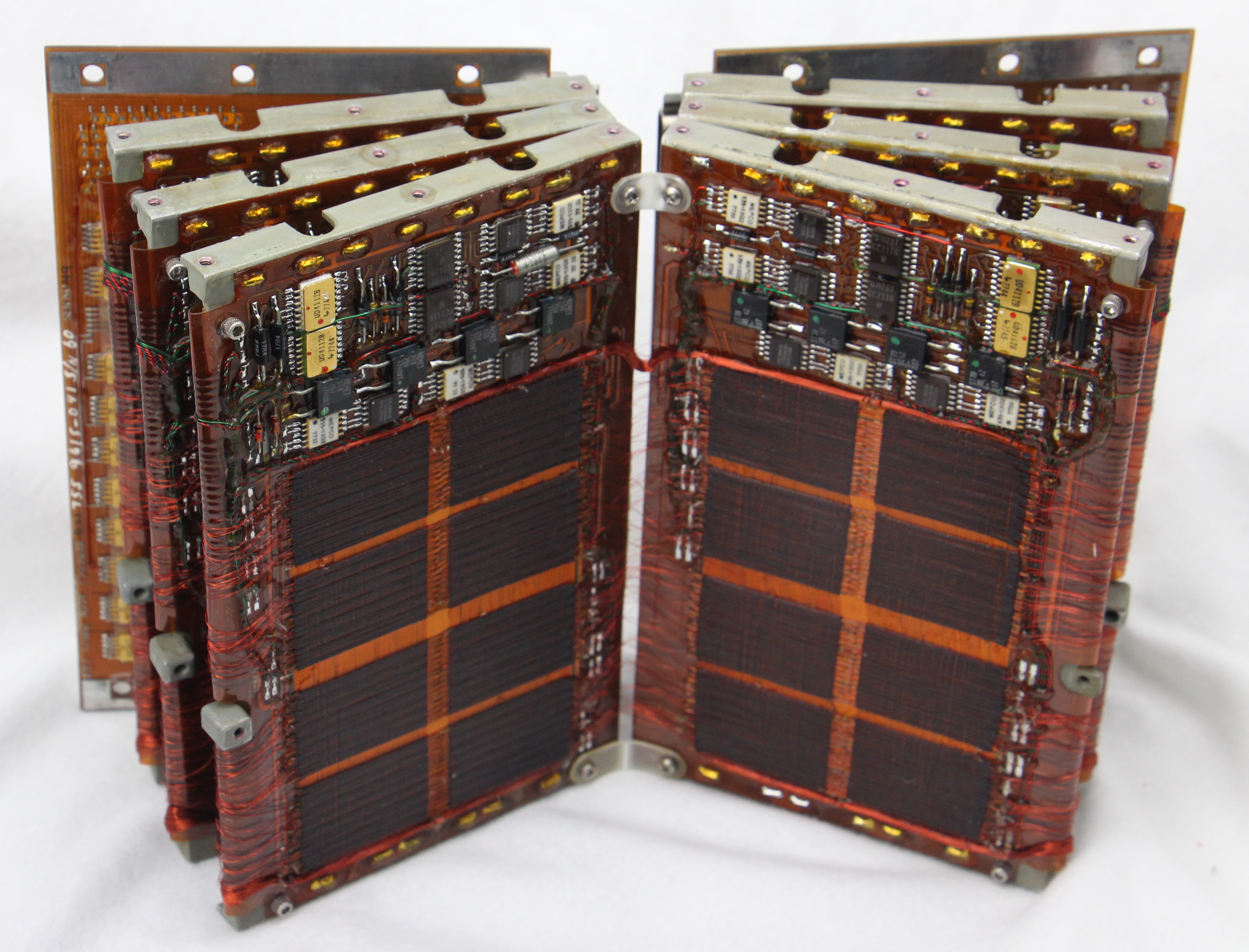
- Figure (core memory): “Titan Missile Core Memory Board,” photograph by Steve Jurvetson, via Wikimedia Commons, licensed CC BY 2.0 — a representative plane of magnetic-core memory of the kind a PDP-8 field was built from. https://commons.wikimedia.org/wiki/File:Titan_Missile_Core_Memory_Board_(49570705568).jpg
.jpg)
Comments (0)