PDP-8/I · Volume 14
PDP-8/I — Volume 14 — Building My PDP-8/I Replica
The capstone: opening the PiDP-8/I kit, taking up the iron to solder its LEDs and switches, dropping a Raspberry Pi behind the panel, and bringing the blinking front panel of a 1968 minicomputer back to life on my own bench.
14.1 About This Volume
Thirteen volumes of history and architecture have all pointed at one quiet moment: the soldering iron coming out of the drawer. Volume 13 ended on the workbench, with the PiDP-8/I described as a kit — a bare board and bags of components — and handed the story off with a single sentence: Volume 14 documents Jeff actually building his PiDP-8/I. This is that volume. The series can no longer be told from the outside, because everything from here is a build, and a build is something you do with your hands.
A caution before the smoke rises. This is meant to be a first-person account of my build, but it is written as a faithful walkthrough of the publicly documented PiDP-8/I assembly process rather than a diary of unverifiable particulars. Where it says “you seat each LED” or “the build begins by,” that is the real, documented procedure, true for anyone who opens the same box — and a frame into which my own specific photos, snags, and small triumphs will later be dropped. What follows is the shape of the build, grounded entirely in what the kit contains and what assembling it actually entails. The rest — the exact evening, the particular joint that went wrong, the look of my panel lit for the first time — is mine to fill in, and will be.
So: the kit on the bench, the iron warming, the panel still dark. Let us build a PDP-8/I.
14.2 The kit as it arrives
What turns up in the post is not a computer. It is a flat, light box, and tipping it open is the first surprise of the project: for an object whose whole purpose is to recreate a 250-pound 1968 minicomputer, there is remarkably little in the bag. The PiDP-8/I, designed by Oscar Vermeulen under the Obsolescence Guaranteed banner, ships as a classic through-hole electronics kit — the kind that was the universal on-ramp to electronics for a generation, and is here deliberately revived as one.
At the centre of everything is a single printed circuit board, the panel board, roughly the footprint of the finished front panel — about two-thirds the size of the original 19-inch-rack PDP-8/I face. Its top surface is a grid of marked positions, and laid over that grid you will eventually read the whole familiar legend: PROGRAM COUNTER, MEMORY ADDRESS, MEMORY BUFFER, ACCUMULATOR, MULTIPLIER QUOTIENT, the rows of state indicators, the bank of data and control switches. Right now it is bare green fibreglass with a constellation of empty holes.
The holes are there to be filled, and most of what fills them is light. The kit’s defining bag is the one heavy with light-emitting diodes — on the order of eighty-nine of them — the modern stand-ins for the original’s incandescent indicator lamps. These are the panel’s entire output: every one corresponds to a single bit of the simulated machine’s registers and state, laid out in exactly the positions Volume 7 walked through, so that the finished panel will report the real register activity of the running processor, lamp for lamp. Eighty-nine small components, each to be placed and soldered, is the bulk of the evening’s work, and the reason the build is mostly an exercise in patient repetition.
The panel’s input arrives in a second weighty bag: around twenty-six toggle switches. These are the part that matters most to the hands. They are genuine miniature toggle switches, not buttons dressed up to look like toggles — the bank of twelve data switches that form the Switch Register, plus the cluster of control switches (Start, Load Address, Deposit, Examine, Continue, Stop, Single Step, Single Instruction) the operator throws to drive the bare machine. The panel was scaled, in fact, around the dimensions of these off-the-shelf switches; the whole replica is sized to fit them. They are what make the difference between looking at a PDP-8/I and operating one.
Around the two big bags is the small-parts ecosystem every kit has: the pin headers — including the long header that will eventually mate the finished panel board to a Raspberry Pi’s GPIO connector — together with whatever resistors, diodes, and mounting hardware the design needs, and the standoffs and screws that hold the sandwich together. There is the panel overlay, the printed legend that lays the PDP-8/I’s iconic graphics over the board so the lights show through in their proper places, and — in the full kits — the case, traditionally a warm, laser-cut bamboo enclosure whose colour deliberately answers the period industrial look. And there is, conspicuously, no computer in the box: the Raspberry Pi that will actually be the PDP-8 is bought separately. The PiDP-8/I is the face; you supply the brain. Almost any reasonably modern Pi will do — the project has tracked the Pi line over the years — and it slots in at the end, behind the finished panel.
That is the whole inventory: a board, eighty-nine lights, twenty-six switches, headers and hardware, an overlay, a case, and a Pi you provide. Everything the entire series has described about the PDP-8/I’s soul is about to be reconstituted from this modest pile. The next step is to turn the iron on.
14.3 The build: a panel, soldered straight
The PiDP-8/I has a well-earned reputation as a good first solder project, and the build bears that out — it is almost entirely through-hole soldering, the forgiving kind, with generously spaced joints and no fiddly surface-mount work demanded of the builder. The project pitches it explicitly at people who have never soldered before, and that is much of its charm: the barrier to owning a PDP-8/I’s front panel is no longer money or rarity or restoration skill, but a few quiet hours and a willingness to learn to lay down a clean joint. What the build asks for is not expertise; it is care, and specifically care about two things — that the lights stand straight, and that the switches sit square.
The lights come first, and they come in volume. Seating eighty-nine LEDs is the long middle of the build, and the discipline the project drills into you from the start is uniformity. Each LED must go in straight — perpendicular to the board — and, crucially, every one must stand at the same height as its neighbours. This is not fussiness for its own sake. The LEDs shine up through the printed overlay, so the panel’s whole appearance depends on them presenting an even face behind the legend: a diode soldered a millimetre too tall, or canted at an angle, will sit proud or crooked under the overlay and betray itself the moment the panel lights. The builder’s trick is to work a row at a time, holding the LEDs flush against the board (a strip of tape, or the overlay itself used as a spacer, keeps a whole row at a common height) while you solder, so that no single light has the chance to slump or lean before its joints set. Place, hold flush, solder both legs, trim, repeat — eighty-nine times. It is meditative more than difficult, and it is the part of the build where the finished panel’s good looks are quietly won or lost.
There is one detail of the lights worth getting right because it is invisible until it isn’t: polarity. LEDs care which way round they go, and a backwards diode simply stays dark. So the repetition is repetition with attention — long leg and short leg, flat side of the package, oriented the same way for every one of the eighty-nine, checked against the board’s markings before the iron touches the joint. Solder is forgiving of a clumsy fillet; it is not forgiving of a part installed backwards once eighty-eight of its siblings are pinning the board down around it.
With the field of lights in, the switches go on, and here the watchword changes from height to square. The bank of toggle switches must be mounted true — aligned in a clean row, each switch upright and at the same angle, so the finished Switch Register reads as the orderly rank of toggles the original had and not a crooked picket fence. The good practice is to seat the whole bank, get it sitting flat and aligned against the board (often by loosely fitting the overlay or front panel over the switch bushings first, so the panel itself jigs them into position), and only then solder, tacking one pin per switch, checking the alignment across the whole row, and committing the rest of the joints once everything is straight. These are the parts the hands will live on; a switch soldered at a tilt is one you feel every time you throw it.
Last comes the part that turns a nice-looking panel into a computer’s face: the GPIO header, the long pin connector that mates the panel board to the Raspberry Pi. This is the electrical handshake between the two halves of the project — every light and every switch on the board ultimately reaches the Pi through this connector — so it wants to be soldered cleanly and, like the switches, perfectly square, because the Pi will press onto it and any lean here fights that mating. With the header on, the panel board is complete: a populated grid of eighty-nine lights and twenty-six switches, an overlay waiting to go over it, a header waiting for a Pi. The hardware is done. What it does not yet have is anything to think.
14.4 The software: a Raspberry Pi and a modified SIMH
The thinking is bought separately and prepared on a memory card. The brain of the PiDP-8/I is the Raspberry Pi, and bringing the panel to life means giving that Pi the right software, because the panel is electrically inert without it — a grid of lights with no idea what to display and switches with nothing reading them.
The software is the SIMH of Volume 12, but modified so that the simulator and the panel are one system rather than two. The project distributes a prepared software image — a complete Raspberry Pi OS (the Pi’s Debian-based Linux) with the modified SIMH PDP-8 already built and configured into it — and bringing the machine up means flashing that image onto a microSD card. The mechanics are the ordinary Raspberry Pi ritual that an entire hobby has standardised: download the image, write it to the card with an imaging tool, slot the card into the Pi. (The community distribution maintained on the tangentsoft.com wiki is the thorough modern source for the software, and it can be built from source onto a fresh OS as readily as flashed from a prepared image — either path lands the same running system on the card.) There is no toggling-in required to get here; the bootstrap problem of Volume 7 is a thing you will recreate later, by choice, on the finished machine — the host Linux loads itself the modern way.
Then the two halves marry. The Pi, card installed, presses onto the panel board’s GPIO header and is fixed behind the panel inside the case, so that the finished object is a sandwich: the printed overlay on top, the populated board beneath it, and the Raspberry Pi tucked behind, all bolted together in the bamboo enclosure. Power goes to the Pi — and at this moment the project’s two cleverest pieces of engineering, both described in Volume 13, come into play for real on your bench.
The first is multiplexing, the trick that lets a Pi’s couple-dozen usable GPIO pins drive eighty-nine lights and read twenty-six switches when there are nowhere near enough pins to wire each one its own line. The panel is built as a matrix: the LEDs are organised into a handful of logical rows, and a tight loop on the Pi lights one row at a time — setting just the LEDs that should be on in that instant — then moves to the next, cycling through all of them hundreds of times a second. No single light is ever continuously lit, but persistence of vision fuses the flicker into a steady, glowing panel. The switches are scanned the same way, row by row, so the same small set of pins both drives the lights and reads the toggles. It is, pleasingly, a software re-creation of exactly the kind of rapid, state-sampling display the original machine’s register lamps amounted to.
The second is the incandescent lamp simulator, and it is the detail that elevates the whole thing from accurate to beloved. A real PDP-8/I did not light its panel with LEDs; it lit it with incandescent bulbs, and a filament does not switch cleanly on and off — it glows up and fades, lagging behind the signal by the thermal inertia of a hot wire. Modern LEDs, left to themselves, snap. So the community (begun by Ian Schofield, refined by Warren Young) wrote software that models that thermal lag, driving the LEDs’ brightness so they imitate not merely which lamps the original lit but the soft rise and decay of the bulbs themselves. The result, when the panel comes up, is a glow with a warmth to it that a bank of bare LEDs never has — the texture of 1968 light, recreated in code. It is the kind of care that explains why this kit, and not a purer or more literal one, is the one that sold in the thousands.
A quiet, honest footnote, in keeping with the project’s own candour: the SIMH underneath actually implements the slightly later PDP-8/e instruction set — a superset of the 8/I’s — so a handful of low-level details differ from a literal 1968 8/I. For everything this series has described, the panel behaves as the 8/I did.
14.5 Bring-up: the panel lights
There is a moment in every build of this kind when the work stops being assembly and becomes a machine, and for the PiDP-8/I it is the first power-on. The card is flashed, the Pi is seated on the header, the case is closed, the overlay is on. You connect power.
The Pi boots into Linux the way any Pi does — invisibly, behind the panel — and then the modified SIMH launches, a dedicated thread begins copying the simulated machine’s register contents out to the LED matrix and reading the switch matrix back into the simulator, and the panel lights for the first time. The incandescent simulation gives it that soft, warm rise rather than a hard snap, and what you are looking at is no longer a craft project: it is the live register activity of a running PDP-8, displayed lamp for lamp in the exact layout Volumes 6 and 7 described. The Program Counter, the Memory Address and Buffer, the Accumulator, the Multiplier Quotient, the state indicators — all of it, glowing and flickering on a panel you soldered an evening ago.
From there the machine is a whole PDP-8 world. Because the host is a full Linux box, the Pi can come up straight into OS/8 — the operating system of Volume 9 — running on the simulated processor, with the panel reporting what the CPU is doing the entire time; you can drive it from a terminal, ssh in over the network, or sit it on the bench and treat the switches as the only interface, exactly as 1968 demanded. The early kits even shipped with the flyer Volume 13 pictured: PLAY WITH THE PiDP — 1969 EXPERIENCE.
And then comes the rite the whole series has been building toward: toggling in a program by hand, on real switches, and watching the lights answer. The procedure is precisely the one Volume 7 taught — set an address in the Switch Register, press Load Address, deposit your words one at a time letting the address self-increment, verify with Examine, then Load Address again and Start. The natural first program is the smallest possible loop, something that does nothing but cycle so you can see the panel run: a couple of words that jump to themselves, or increment forever, so that when you press Start the address lamps dissolve into the dim, characteristic shimmer of a tight loop — the same shimmer an operator read the health of a program from in 1968, now flickering under your own fingers. Throw Stop and it freezes, every register held up in light for you to read in octal. You can deposit a slightly larger program — the four-word adder of Volume 7, perhaps, set five and three into two locations, run it, and read 0010 off the Accumulator — and watch a machine you built do arithmetic and report it in lamps.
When the toggling palls, the higher-level world is right there too: drop into OS/8 and start FOCAL, DEC’s terse little interactive language, or BASIC, and the same machine that you were just programming a bit at a time through twelve switches will take typed lines and run them. The whole stack of the series — the bare switches at the bottom, the loaders, the operating system, the interpreters — is present and alive in a single object on the bench, and you climbed it yourself, from the soldering iron up.
14.6 The payoff: what blinkenlights teach that a window cannot
Here is the question Volume 13 opened with, asked again now that the panel is built and lit: if SIMH already runs all of this, perfectly, for free, in a window on any laptop — why solder eighty-nine lights to a board? I have the answer in front of me now, glowing, and it is the same answer the whole series has been circling.
A SIMH window reproduces the behaviour of a PDP-8 and discards its entire form. It can show you a register’s value as text; it cannot let you watch it flicker. And the flicker turns out not to be decoration — it is information of a kind the number never carries. The dim shimmer of a tight loop, the steady glow of a halt, the texture of the address lamps under a running program: these are glanceable. The built panel sits on the bench and tells you, at a sideways look from across the room, what the machine is doing — running, stopped, looping, waiting — in a way no scrolling terminal ever will. The original operators read the health of their programs from that texture before they ever stopped to inspect a value, and standing at the finished PiDP-8/I you find yourself doing the same, almost without deciding to. The lights are an interface to the machine’s state of mind, and they only work as light.
Then there are the switches. To toggle a program in by hand — to set an address with your fingers, throw Deposit, feel the click, watch the Memory Address step — is to learn the machine in your body in a way that typing a command in a simulator forecloses. Volume 11 argued that the PDP-8’s deepest bequest was tactile: a computer you learned by touching. You cannot touch a window. The replica gives the touching back, and with it the specific, humbling knowledge of what it meant that every program once had to be coaxed into a cold machine one bit at a time. You do not understand the bootstrap problem until you have toggled sixteen words of RIM loader in by hand on real switches and felt how badly you want a better way. The panel teaches that in the only language it can — your fingers.
And there is the plain fact of owning it. Not a photograph of a PDP-8/I, not a simulation of one behind glass in a museum or behind pixels on a screen, but its actual panel — real switches, real lights, real warmth in the glow — sitting on my own bench, running the real OS/8 underneath my fingers, built by my own hand. That is the thing the entire series argued for and could only describe until now: the machine made present. Cheap enough to own, faithful enough to satisfy, and assembled rather than bought, so that the knowing of it runs all the way down to the solder joints.
The wheel comes full circle here, and it is worth saying plainly where it started. The PDP-8 was the machine that took the computer out of the air-conditioned glass house and put it on a bench, in a lab, within reach of an ordinary person’s hands — the machine that made computing tactile and cheap and yours. Fourteen volumes later, the way we honour that is to do exactly the same thing again with the same machine: take it out of the museum, make it cheap, and put it back on a bench under our own hands, soldered together from a bag of parts. The democratizing instinct the PDP-8 set loose in 1968 is the very instinct that, in 2026, hands you a kit and a soldering iron and says: build one yourself.
So that is where the series ends — not with a fact about a machine, but with the machine itself, lit and clicking and warm, on the bench where it belongs. The history is told. The architecture is mapped to the gate. The front-panel ritual is in the fingers. And the panel that thirteen volumes called the soul of the PDP-8/I is no longer a thing to be read about. It is a thing I built, and it is blinking in front of me. Throw a switch. Watch the lights answer. That is the whole of it, and it was always the point.
Sources
- Obsolescence Guaranteed (Oscar Vermeulen), “PiDP-8” project and build pages — the PiDP-8/I as a Raspberry-Pi-based replica of the PDP-8/I front panel running a modified SIMH, sold as an easy-to-build through-hole kit explicitly suitable for first-time solderers; the kit’s contents (panel PCB, the bank of LEDs and toggle switches, headers, overlay, bamboo case), the separately-supplied Raspberry Pi, and the prepared software image. https://obsolescence.dev/pidp8.html · https://obsolescence.wixsite.com/obsolescence/pidp-8-overview
- Obsolescence Guaranteed (Oscar Vermeulen), “How to use the PiDP-8” — operating the finished panel: the front-panel switches and the hand-toggled bootstrap (RIM/BIN), confirming that the built replica is driven exactly as the original was, used here for the bring-up / first-program walkthrough. https://obsolescence.dev/pidp-8-how-to-use.html
- Raspberry Pi Foundation, “PiDP-8/I — remaking the PDP-8/I” — overview confirming the design: a Raspberry Pi running Raspberry Pi OS and a SIMH emulator modified to reflect PDP-8 CPU register state through the panel LEDs and to read the switches; open-source hardware; the Pi as the supplied-separately brain behind the panel. https://www.raspberrypi.com/news/pidp-8i-remaking-the-pdp-8i/
- tangentsoft.com, “PiDP-8/I Software” wiki and repository (Warren Young, Bill Cattey, and contributors) — the comprehensive community software distribution and documentation: the ≈89 LEDs and 26 switches and the LED/switch matrix multiplexing scanned in logical rows from the Pi’s ~25 GPIO pins; the Incandescent Lamp Simulator (originally Ian Schofield, improved by Warren Young) modeling filament glow/fade; the note that the simulated CPU implements the later PDP-8/e instruction set; flashing/building the OS image with OS/8, FOCAL and BASIC. https://tangentsoft.com/pidp8i/ · https://tangentsoft.com/pidp8i/wiki?name=Incandescent+Lamp+Simulator · https://github.com/tangentsoft/pidp8i
- Hackaday.io and Hackster.io PiDP-8/I project pages — independent write-ups of the kit, its Raspberry-Pi-plus-SIMH design, the ~2:3 panel scale, the through-hole build, and its reputation as an approachable beginner solder project. https://hackaday.io/project/4434-pidp-8x2fi · https://www.hackster.io/obsolescence/pidp-8-a-pdp-8-minicomputer-on-raspberry-pi-8a7b5a
- This series, Volume 13 (the PiDP-8/I described as a kit and the hand-off to this volume), Volume 12 (SIMH, the emulated core under the panel), Volume 11 (the tactile, democratizing ethos the replica restores), Volume 9 (OS/8, FOCAL, BASIC), and Volume 7 (the front-panel switches and lamps and the hand-toggled first program reproduced here on the finished replica). The build/operation facts in this volume — kit contents, ≈89 LEDs / 26 switches, Raspberry-Pi-plus-SIMH core, OS/8 and the front-panel ritual — trace to those volumes and the sources above.
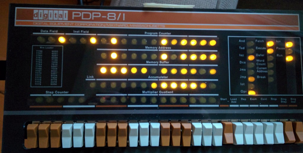
- Figure (placeholder): “PiDP-8 running Adventure,” photograph by leighklotz, via Flickr / Openverse, licensed CC BY 2.0 — a finished, powered PiDP-8/I with the panel lit and a program running; stock placeholder to be replaced with Jeff’s own build photo. https://www.flickr.com/photos/7417392@N05/24730565084
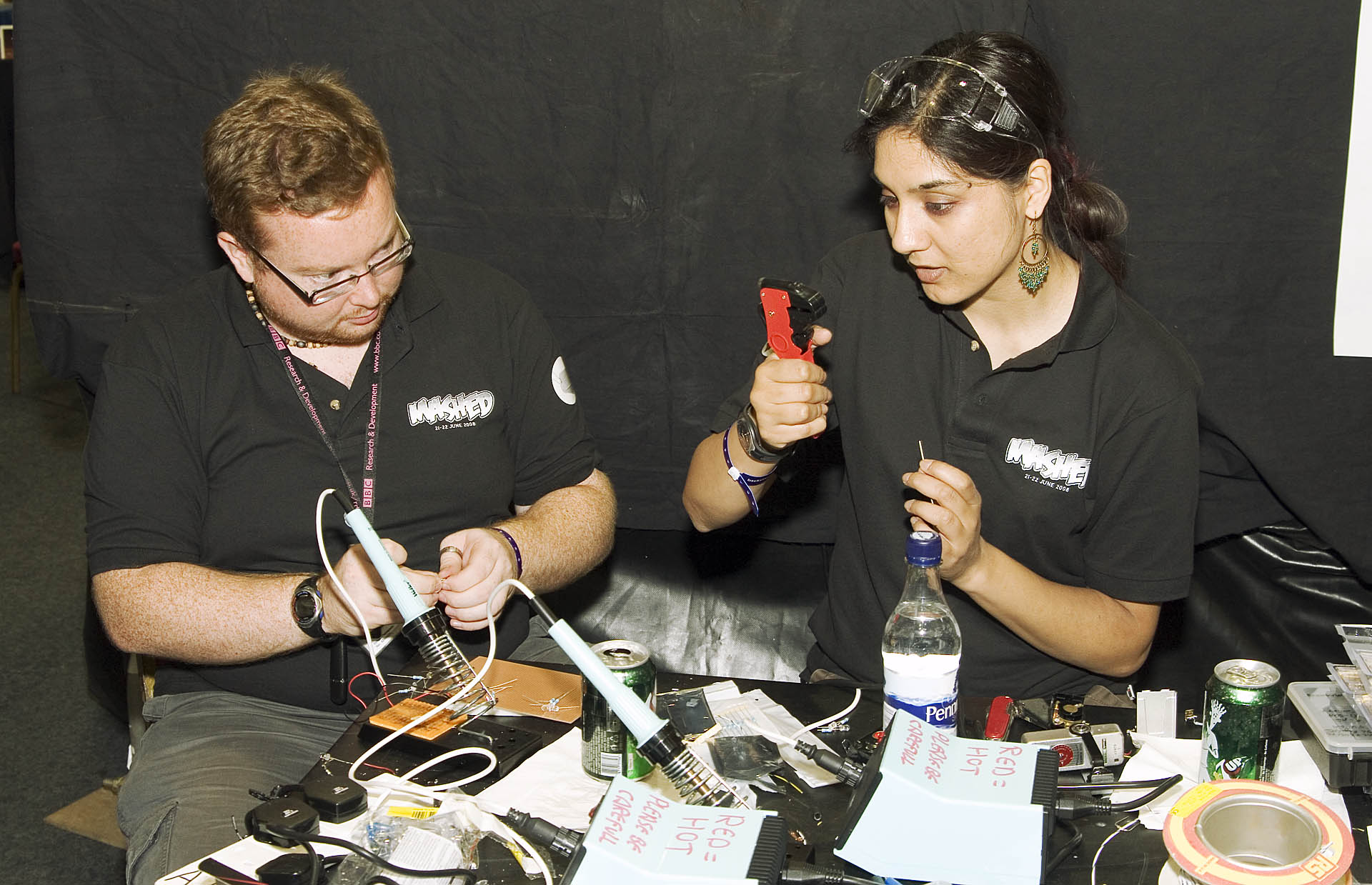
- Figure (placeholder): “Electronics from Mashed 08,” photograph by mashed2008, via Wikimedia Commons, licensed CC BY-SA 2.0 — a through-hole circuit-board soldering scene standing in for the PiDP-8/I assembly; stock placeholder to be replaced with Jeff’s own build photo. https://commons.wikimedia.org/wiki/File:Electronics_from_Mashed_08.jpg
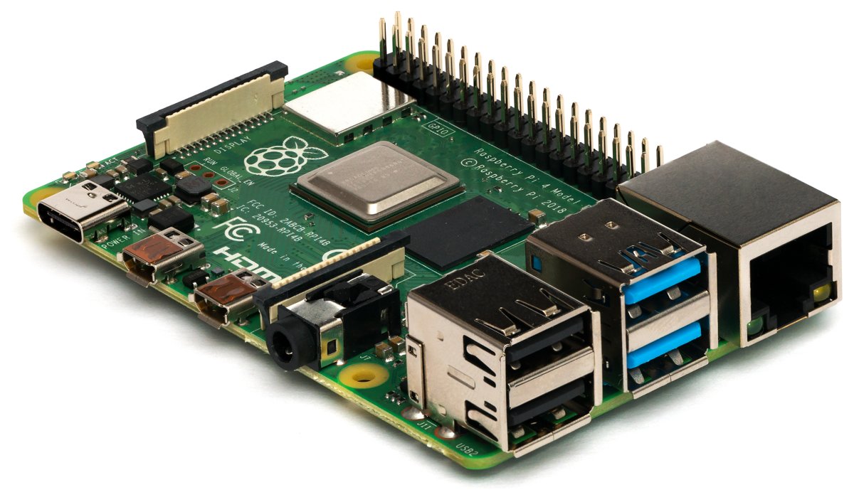
- Figure (placeholder): “Raspberry Pi 4 Model B - Side,” photograph by Laserlicht, via Wikimedia Commons, licensed CC BY-SA 4.0 — the Raspberry Pi single-board computer that becomes the processor behind the panel; stock placeholder to be replaced with Jeff’s own build photo. https://commons.wikimedia.org/wiki/File:Raspberry_Pi_4_Model_B_-_Side.jpg
Comments (0)