PDP-8/I · Volume 7
PDP-8/I — Volume 7 — Programming the Front Panel
How an operator with nothing but twelve toggle switches and a wall of lamps could talk to a bare machine, hand-build a program a word at a time, and toggle in the tiny loader that taught the computer to read its own paper tape.
7.1 About This Volume
Volume 6 left the front panel sitting at the front of the slide-out chassis as a piece of hardware: a horizontal row of toggle switches wired straight into the logic, a grid of incandescent lamps wired straight off the flip-flops, the one face of the box built for human hands and eyes. This volume puts those hands on it. The panel is where a person and a PDP-8/I actually meet, and learning to drive it is learning the oldest and most intimate skill in the whole craft — the way every one of these machines was woken up, fed a program, watched as it ran, and debugged when it misbehaved, in an age before a keyboard and screen were anything you could take for granted.
It is a curiously physical kind of programming. There is no editor, no compiler, no operating system between you and the machine — not yet, because the very thing this volume builds toward is getting the first program into a computer that, switched on cold, contains nothing at all. We start with the controls themselves: the twelve data switches of the Switch Register and the cluster of control switches around them, and the lamps that report the machine’s living state. We learn the operator’s core loop — depositing and examining memory by hand, one word at a time, with the address quietly stepping itself forward. We learn to read a running machine by its lights, in octal, and to single-step it instruction by instruction to watch a program think. And then we confront the deep puzzle the panel exists to solve: the bootstrap problem — how a machine that needs a program in memory to read a tape can ever read the first tape — and the beautiful two-stage answer DEC built around it, the RIM and BIN loaders. By the end you will be able to walk up to a cold PDP-8/I and, with nothing but your fingers, bring it to life.
7.2 The controls: the Switch Register and its companions
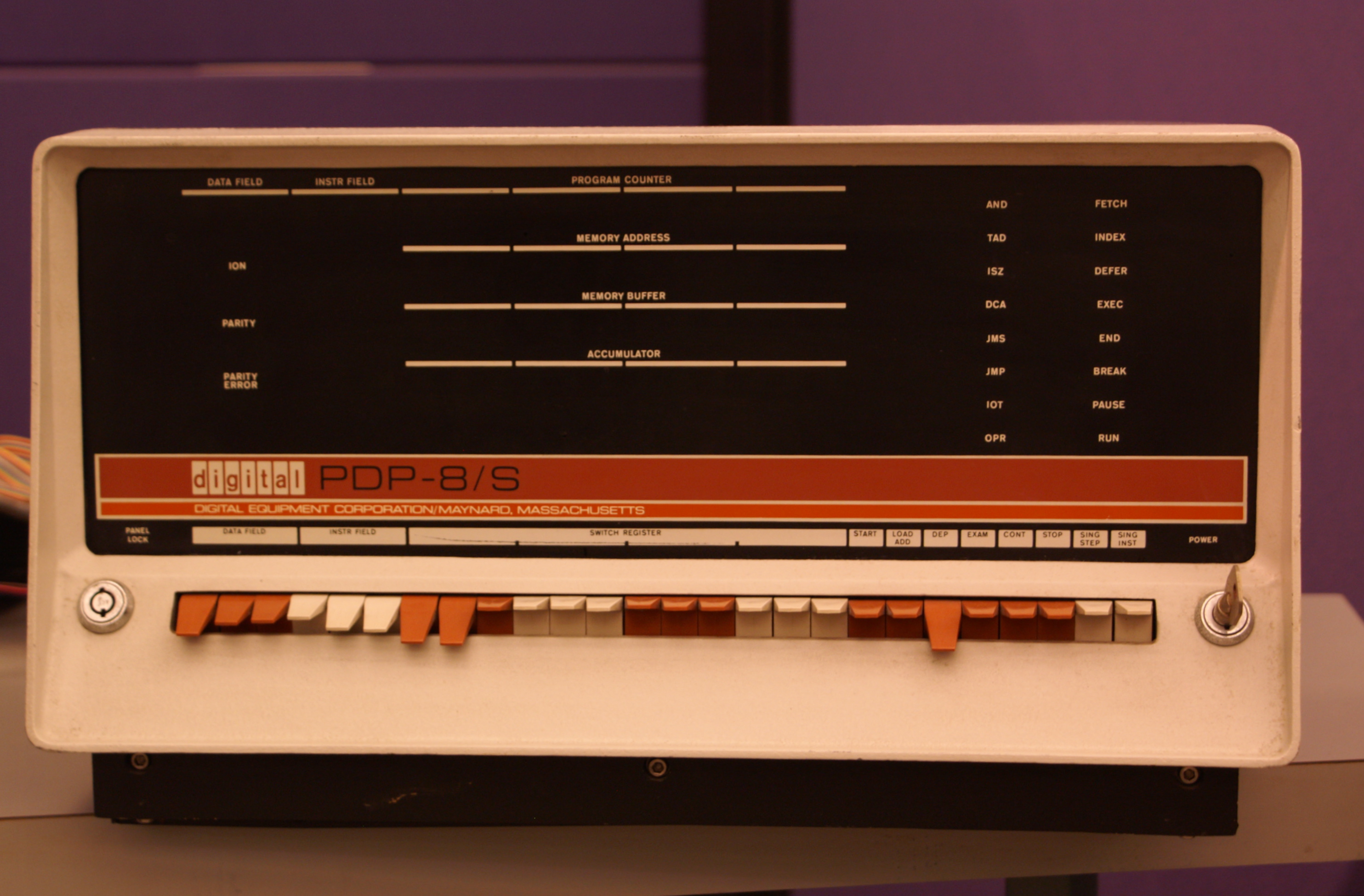
Everything on the panel divides into two populations: switches, by which you put information into the machine, and lamps, by which the machine shows information to you. Take the switches first.
The heart of the input side is the Switch Register, the SR — a horizontal row of twelve toggle switches, met already in Volume 4 as a register the program can read. Each switch is one bit. Flip it up and that bit is a 1; leave it down and it is a 0. Together the twelve switches hold a twelve-bit value that you set with your fingers, and that value sits there, statically, until you change it — the SR is the operator’s hand permanently resting on twelve bits of the machine. Because twelve bits is exactly four groups of three, the switches are physically clustered in fours of three, so the row reads naturally as four octal digits: a value like 0200 is just the leftmost three switches showing 000, then 010, then 000, then 000. This grouping is not decoration; it is the whole reason the PDP-8 world speaks octal, and it makes setting a number by hand a matter of dialing four small digits rather than juggling twelve loose bits.
Around the Switch Register sits a cluster of control switches — these are momentary push-toggles, not the static data switches; you flick one and it springs back, having told the machine to do something now. The PDP-8/I’s set, reading across the bottom of the panel, are these:
- Load Address (often legended
LOAD ADD) — take whatever twelve-bit value is standing in the Switch Register and copy it into the machine’s address register, so the panel is now “pointing at” that memory location. This is how you tell the machine where you want to work. - Deposit (
DEP) — take the value standing in the Switch Register and write it into the memory location the panel is pointing at, then advance the pointer by one. This is how you put a word into memory. - Examine (
EXAM) — read the word at the location the panel is pointing at, display it in the lamps, then likewise advance the pointer by one. This is how you read a word out of memory. - Start — begin running the program, from the address the panel is pointing at. (On the PDP-8/I, Start also clears the accumulator and the link as it goes, giving a program a clean slate to begin from.)
- Stop / Halt — stop the running machine cleanly at the end of the current instruction, freezing its state in the lamps so you can read it.
- Continue (
CONT) — resume a stopped machine from exactly where it left off, without clearing anything, so a program halted at a breakpoint can be picked up again. - Single Step and Single Instruction — the two “slow motion” switches. Single Instruction (sometimes legended
SING INST) runs the program forward by exactly one whole instruction and then stops, so you can step through a program one instruction at a time and watch each one’s effect in the lamps. Single Step advances the machine by one internal memory cycle — a finer grain still, letting you watch a single instruction unfold through its fetch and execute phases. (Exact switch nomenclature drifts a little across the PDP-8 family — a later 8/e labels some of these differently, and some panels gang “step” and “instruction” onto one switch with a mode selector — but the 8/I carries this set, and the functions are constant across the line.)
A power key and a panel lock usually finish the row, guarding against an idle finger nudging a switch on a running machine.
Now the output side: the indicator lamps. These are rows of small incandescent bulbs, each wired directly to a flip-flop inside the machine, so that a lit lamp means that bit is currently a 1 and a dark lamp means it is a 0 — live, changing in real time as the machine runs (or, when it runs fast, blurring into a steady glow). The PDP-8/I brings out the machine’s whole nervous system this way. The principal rows are:
- the Program Counter (PC) — twelve lamps showing the address of the next instruction to be fetched;
- the Memory Address (MA) — twelve lamps showing the address the machine is currently reaching into; this is the register Load Address loads and that Deposit and Examine step;
- the Memory Buffer (MB) — twelve lamps showing the word currently passing to or from memory;
- the Accumulator (AC) — twelve lamps showing the contents of the single accumulator of Volume 4, the machine’s working register;
- the Link (L) — a single lamp for the one-bit link flip-flop that catches carries out of the accumulator;
- and a bank of state lamps — small status lights for the major states of the processor (the fetch, defer, and execute phases an instruction passes through), for whether interrupts are on, and, crucially, a RUN lamp that is lit while the processor is executing and dark while it is halted. (The 8/I, generously equipped, also displays the MQ — the multiplier-quotient register — and several more internal states; the list above is the operator’s working subset.)
The panel, then, is the machine turned inside out: the switches are the operator’s grip on the address and data lines, and the lamps are the registers held up to the light.
   PROGRAM COUNTER     o o o   o o o   o o o   o o o
   MEMORY ADDRESS      o o o   o o o   o o o   o o o      lamps
   MEMORY BUFFER       o o o   o o o   o o o   o o o      (each = 1 bit;
   ACCUMULATOR   (L o) o o o   o o o   o o o   o o o       lit = 1)
   MULT. QUOTIENT      o o o   o o o   o o o   o o o

   state:  ( FETCH )( DEFER )( EXECUTE )   ( ION )   ( RUN )

   SWITCH REGISTER      ^   ^   ^     ^   ^   ^     ^   ^   ^     ^   ^   ^
                        |   |   |     |   |   |     |   |   |     |   |   |   toggles
                        0   1   2     3   4   5     6   7   8     9  10  11   (up = 1)
                       \____ ____/   \____ ____/   \____ ____/   \____ ____/
                            v             v             v             v
                         octal d1      octal d2      octal d3      octal d4

   ( START ) ( LOAD ADDR ) ( DEP ) ( EXAM ) ( CONT ) ( STOP ) ( SS ) ( SI )
7.3 Depositing and examining memory by hand
With the controls named, the operator’s fundamental loop falls out. The machine’s memory is four thousand-odd numbered pigeonholes; the panel lets you write a value into any one and read a value back from any one, and the trick that makes it bearable is that the address steps itself.
Suppose you want to place a value into location 0200. You set 0200 in the Switch Register — three switches dialed to read the four octal digits 0, 2, 0, 0 — and press Load Address. The Memory Address lamps now read 0200: the panel is pointing there. Now you set the value you want to store in the Switch Register — say 7200 — and press Deposit. The machine writes 7200 into location 0200, and then increments the address: the Memory Address lamps now read 0201. You have not had to touch Load Address again. To fill the next location you simply dial the next value into the SR and press Deposit once more; it lands in 0201 and the pointer steps to 0202. Successive deposits, each just “set value, press Deposit,” march straight down through consecutive memory — which is exactly how a program, a sequence of words in adjacent locations, gets toggled in.
Here is a complete, real example: a tiny program that adds two numbers and halts. We toggle it in starting at 0200.
   addr / contents   mnemonic     what it does
   ----   --------   --------     ------------------------------------
   0200 /  7200      CLA          clear the accumulator to 0
   0201 /  1206      TAD 0206     add the word at 0206 into AC
   0202 /  1207      TAD 0207     add the word at 0207 into AC
   0203 /  7402      HLT          halt the processor
   0204 /  0000                   (unused)
   0205 /  0000                   (unused)
   0206 /  0005      operand A  = 5 (octal)
   0207 /  0003      operand B  = 3 (octal)
The ritual to enter it is mechanical: set 0200 in the SR, press Load Address; now set 7200, Deposit; set 1206, Deposit; set 1207, Deposit; set 7402, Deposit; Deposit 0000 twice for 0204–0205; set 0005, Deposit; set 0003, Deposit. Eight values, eight presses of Deposit, and the program is in core — and, because core memory is non-volatile (Volume 6), it will stay there through a power cycle.
The inverse operation, Examine, reads memory back the same way, and is how you check your work — an indispensable habit, because a single mis-dialed switch silently corrupts one word. Set 0200 in the SR, press Load Address, then press Examine: the lamps show the contents of 0200 (you should see 7200) and the address steps to 0201. Press Examine again: you read 0201 (1206) and the address steps to 0202. Walking Examine down the locations, you compare what the lamps show against your listing; if word 0202 comes back as 1007 instead of 1207, you have found your typo, and you re-deposit just that one location to fix it. This deposit-to-write, examine-to-verify dance, both riding on the self-incrementing address, is the entire manual-memory workflow — the reason the PDP-8 community could speak of “toggling in” a program as a routine, if tedious, act.
To run what we just entered: set 0200 in the SR, press Load Address to point the machine at the program’s start, then press Start. The processor clears the accumulator and the link and begins fetching at 0200. It clears AC, adds 5, adds 3, and hits the HLT — all in a few microseconds, far faster than the eye — and stops. The RUN lamp goes dark, and the Accumulator lamps freeze showing the answer: 0000 0000 1000 in binary, which the eye, reading the lamps in their groups of three, takes in as octal 0010 — eight, the sum of five and three. The machine has done arithmetic, and reported it in light.
7.4 Reading the lights
That last step — glancing at a row of lamps and seeing a number — is a skill of its own, and it is built on octal. The lamps are binary: each is on or off, a 1 or a 0. But twelve loose bits are hard for a person to hold, so the PDP-8 operator never reads them as twelve; the lamps, like the switches, are spaced in four groups of three, and each group of three lamps is read as a single octal digit (000=0, 001=1, 010=2, 011=3, 100=4, 101=5, 110=6, 111=7). A glance converts each triple to a digit and the row becomes four octal digits. The Accumulator showing 001 010 011 100 is not a wall of bits but simply 1234. With a little practice the conversion becomes automatic, and an operator reads the registers off the panel as fluently as reading a clock — which is precisely why the whole architecture was laid out in octal and why DEC printed its software listings, its loaders, and its reference cards in octal throughout.
Reading the lights is how you understand a running machine, and the panel is generous about it. While a program runs at full speed the address-bearing lamps — the PC and MA — flicker too fast to resolve and settle into a dim, characteristic shimmer; an experienced operator could read the health of a program from the texture of that shimmer, recognizing a tight loop or a runaway by its pattern of glow before ever stopping the machine. And when something is wrong, the panel becomes a debugger. Press Stop, and the machine halts at the end of its current instruction with every register frozen in the lamps: you read the PC to see where it stopped, the AC and Link to see what it was holding, the MA and MB to see what it was touching. From there, Examine lets you walk through memory inspecting variables and instructions, and Deposit lets you patch a word on the spot — change an instruction, correct a constant — without re-entering the whole program.
The finest-grained tool is single-stepping. Instead of pressing Start and letting the program blur past, you point the machine at the start and press Single Instruction repeatedly. Each press executes exactly one instruction and stops, and between presses the lamps sit still, showing you the exact effect of that one instruction: the PC advancing by one (or jumping), the AC changing as a TAD adds or a DCA clears it, the Link flipping on a carry. You walk your program forward at the speed of human attention, one instruction per press, watching the machine think — and the moment a register holds something you did not expect, you have found the instruction that did it. The still-finer Single Step switch advances by a single internal memory cycle rather than a whole instruction, exposing the fetch-and-execute phases of one instruction for the deepest hardware-level diagnosis. This — halt, read the registers, examine memory, single-step the suspect code, patch and continue — was the debugging method of the era, conducted entirely in light and octal on the face of the machine.
7.5 The bootstrap problem and the RIM loader
Everything so far assumed you were willing to toggle a program in by hand. For a four-word adder that is fine. For real software — an assembler, a FORTRAN compiler, a game — running to thousands of words, toggling by hand is out of the question; that software arrived on punched paper tape, to be read in through the Teletype’s tape reader. But this raises a deep and genuinely circular problem.
To read a paper tape, the machine must run a program that drives the reader — a program that says, in effect, “fetch a frame from the tape, store it in memory, fetch the next, store it, and so on.” That tape-reading program is itself a program, and it has to be in memory before it can run. So: to load a program from tape you need a loader in memory; but to get the loader into memory you would want to load it from tape; but to load that you need a loader already in memory… A machine switched on cold has empty (or garbage) core and no way to read the very tape that would fill it. This is the bootstrap problem — pulling yourself up by your own bootstraps — and every stored-program computer faces some version of it.
The PDP-8’s answer is to make the first loader small enough to enter by hand. If the tape-reading program can be squeezed down to a handful of words, an operator can toggle those few words into memory through the front panel — using exactly the Deposit ritual above — and that hand-entered program is then enough to read a tape. This minimal hand-toggled loader is the RIM loader — RIM for Read-In Mode, the simple tape format it understands — and it is justly famous for its brevity: just sixteen twelve-bit words. Here is the canonical RIM loader for the low-speed Teletype paper-tape reader (device 03), exactly as DEC printed it, occupying the top of memory at 7756–7775:
   addr / contents          addr / contents
   ----   --------          ----   --------
   7756 /  6032             7766 /  7006
   7757 /  6031             7767 /  6031
   7760 /  5357             7770 /  5367
   7761 /  6036             7771 /  6034
   7762 /  7106             7772 /  7420
   7763 /  7006             7773 /  3776
   7764 /  7510             7774 /  3376
   7765 /  5357             7775 /  5356
These sixteen words are pure loader. Most are IOT instructions talking to the Teletype reader — 6031 is skip if the reader has a character ready, 6032 clears the reader and the accumulator, 6034 and 6036 read a character into the accumulator — interleaved with rotates (7106, 7006) that shift the six bits of a tape frame into position and a deposit-indirect (3776) that stores each assembled word into memory through a pointer. In plain terms: it waits for the reader flag, reads a frame, tests whether the frame is an address or a data word (a RIM tape alternates the two), assembles the six-bit frames into twelve-bit words, and deposits each word at the address the tape names — then loops for the next. A RIM-format tape is therefore a bare sequence of address/value pairs, and these sixteen words are just enough machinery to unpack them into core. (A second, near-identical variant exists for the optional high-speed photoelectric reader — device 01 — differing only in the device codes it uses, 6011/6014/6016 in place of 6031/6032/6034/6036; the structure is the same. The high-speed RIM loader begins 7756/6014, 7757/6011, the give-away by which an operator could tell at a glance which reader a toggled-in loader was built for.)
To use it, the operator toggles all sixteen words in by hand — set 7756, Load Address, then Deposit the column above, value by value — verifies them with Examine, then sets the SR to 7756, presses Load Address and Start, and feeds the RIM-format tape into the reader. The little program springs to life and pulls the tape into memory.
7.6 The BIN loader and the layered bootstrap
The RIM loader works, but it is deliberately primitive. RIM format is wasteful of tape — every data word must be preceded by its full address, and there is no error checking — so it is a poor format for shipping real software. What you actually want is a smarter, more compact loader: the BIN loader (Binary loader), the general-purpose program that reads the dense, checksummed binary-format tapes that essentially all PDP-8 software was distributed on. BIN format packs words efficiently, lets a tape name a starting address once and then stream consecutive words, and ends with a checksum so the loader can verify the tape read in correctly — everything RIM format lacks.
But the BIN loader is itself a couple of hundred words long — far too much to toggle in by hand. And here the design reveals its elegance: you do not toggle in the BIN loader. You toggle in the sixteen-word RIM loader, and then use RIM to read in the BIN loader from a paper tape. The BIN loader is distributed as a short RIM-format tape precisely so that the hand-entered RIM loader can read it; once RIM has pulled BIN into memory (it settles into locations 7625–7752, just below RIM’s own perch), the machine has a full-strength loader resident, and from then on every other tape — the assembler, the editor, your own programs — is a binary tape that the BIN loader reads.
So the bootstrap is layered, each stage just powerful enough to load the next:
- Hands → RIM. The operator toggles the sixteen-word RIM loader in through the front panel. This is the only stage done by hand, and it is kept tiny on purpose.
- RIM → BIN. RIM is started and reads the BIN loader’s RIM-format tape, placing the full binary loader into high memory.
- BIN → your program. BIN is started and reads the efficient, checksummed binary tape of whatever you actually wanted to run.
Three stages, climbing from sixteen words of finger-work to a real loader to real software — each rung built by the rung below it, which is why the pattern is called bootstrapping. It was layered this way for one reason: the only part that must be entered the hard way, by hand, is kept as small as it possibly can be — sixteen words a person can toggle and verify in a few minutes — while all the comfort and capability lives in the larger loaders the small one fetches automatically.
For the people who ran these machines, this was not an abstraction but a morning ritual. Core memory is non-volatile, so on a machine left undisturbed the RIM and BIN loaders survived overnight in their high-memory homes, and the day might start with nothing more than loading a program tape through BIN. But after a power failure, a crash that scribbled over high memory, or any morning the machine came up cold, the ritual ran in full: stand at the panel and toggle the sixteen words of RIM in from memory — many operators knew the pattern by heart — verify them with Examine, start RIM and feed it the BIN tape, then start BIN and feed it the day’s work. Switches up and down, lamps blinking, paper tape clattering through the reader: that was how you said good morning to a PDP-8/I, and it is the physical reality the clean abstractions of the earlier volumes were always, underneath, made of. The next volume leaves the panel behind and turns to the machine’s voice to the outside world — the Teletype, paper tape, and the programmed-I/O that the RIM loader has just given us our first glimpse of.
Sources
- Doug Jones, “DEC’s 1974 PDP-8 Pocket Reference Card” (University of Iowa), giving the canonical RIM loader octal listings verbatim — the low-speed/Teletype (device 03) loader at
7756–7775(6032, 6031, 5357, 6036, 7106, 7006, 7510, 5357, 7006, 6031, 5367, 6034, 7420, 3776, 3376, 5356) and the high-speed reader (device 01) variant beginning7756/6014, 7757/6011. The values quoted in this volume are taken directly from this card. https://homepage.divms.uiowa.edu/~jones/pdp8/refcard/74.html - Doug Jones, PDP-8 boot/loader and instruction pages (University of Iowa) — the RIM and BIN loader concepts, RIM-format versus binary-format tapes, and the device IOT codes (
6031/6032/6034/6036for the keyboard/low-speed reader). https://homepage.cs.uiowa.edu/~jones/pdp8/ · https://homepage.cs.uiowa.edu/~jones/pdp8/man/mri.html - Obsolescence Guaranteed (Oscar Vermeulen), “How to use the PiDP-8” — the two-stage bootstrap as a lived procedure on the PiDP-8/I replica: hand-toggle and verify the RIM loader at
7756–7775(checking, e.g.,6014at7756and6011at7757for the high-speed variant), use RIM to read the BIN loader (which occupies7625–7752and7777), then use BIN to read application tapes. https://obsolescence.dev/pidp-8-how-to-use.html - “SIMH PDP-8: Manually Loading the RIM Loader, the Binary Loader, and an Application from Paper Tape,” Big Dan the Blogging Man — a step-by-step walk-through of toggling RIM in, loading BIN with it, and then loading an application, corroborating the layered bootstrap and the front-panel Deposit/Examine/Load-Address/Start procedure. https://bigdanzblog.wordpress.com/2014/06/17/simh-pdp-8-manually-loading-the-rim-loader-the-binary-loader-and-an-application-from-paper-tape/
- PDP-8/I & PDP-8/L Small Computer Handbook and the PDP-8 Family Paper Tape System User’s Guide (Digital Equipment Corporation), via bitsavers.org — DEC’s own documentation of the front-panel switches (Switch Register, Load Address, Deposit, Examine, Start, Stop, Continue, Single Step / Single Instruction), the indicator lamps (PC, MA, MB, AC, Link, state), the auto-incrementing Deposit/Examine behavior, and the RIM and BIN loaders. http://www.bitsavers.org/pdf/dec/pdp8/ · http://www.vaxhaven.com/images/6/6f/DEC-08-NGCC-D.pdf
- Wikipedia, “PDP-8” — corroborates the twelve-bit Switch Register and indicator lamps as the operator interface, octal reading of the panel, and the hand-toggled RIM loader / paper-tape BIN loader bootstrap. https://en.wikipedia.org/wiki/PDP-8
- Figure: “PDP-8/s,” photograph by ajmexico at the Computer History Museum (Mountain View), via Wikimedia Commons, licensed CC BY 2.0 — a running PDP-8-family front panel of switches and indicator lamps. https://commons.wikimedia.org/wiki/File:PDP-8_s_(2682618330).jpg
.jpg)
Comments (0)